1.1 Ion sources and primary column
The IMS 7f-Auto is equipped with an in-line ion optical primary column, which consists of a set of electrostatic ion optical devices for focusing and deflecting the primary ion beam, aperture diaphragms, and a Faraday cup for accurate primary ion current measurement. A differential pumping stage ensures UHV sample environment during analysis. The primary column is fully computer controlled with motor driven apertures and automatic gate valves.
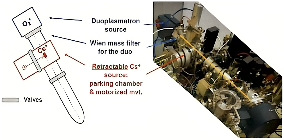
A source chamber allows simultaneous mounting of a high brightness (cold cathode) Duoplasmatron source producing O₂⁺, O⁻, O₂⁻ ions, and of a high brightness (thermo-ionization) Cesium microbeam source producing Cs⁺ ions.
The oxygen beam is particularly efficient for optimizing the sensitivity for electropositive element analysis, whereas the cesium beam enhances the sensitivity for electronegative element analysis.
The source chamber is equipped with a Wien mass filter to be used with the duoplasmatron source for removal of parasitic primary ion species, while the Pseudo Wien Filter (PWF) is used as a mass filter to eliminate spurious elements generated in the Cs ion source, such as Carbon and Oxygen.
The duoplasmatron source is fixed and mounted at the top, in-line with the primary ion column. An accel-decel extraction system is fitted between the source and the Wien mass filter, which makes possible to run analyses with O₂⁺ primary ions at an impact energy as low as 500eV.
The cesium microbeam source is retractable; it moves between the parking chamber (when not used for analysis) and the working position, in-line with the primary column. Cesium source transfer between parking and working positions is fully computer controlled.
Both duoplasmatron source chamber and cesium parking chamber are isolated from the primary column with gate valves and pumped out by their own turbomolecular pump. Thus, the maintenance of a given source can be performed while working with the other source. Switching source operation as well as the start-up and turn-off of the sources are fully computer controlled.
1.1.1 Available parameters
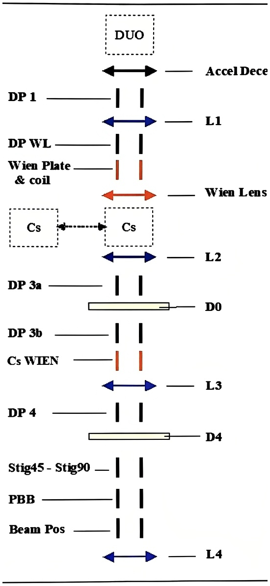
Section titled “1.1.1 Available parameters”The extraction electrode of both sources is connected to the ground potential of the instrument, while the duoplasmatron and Cesium gun assembly (ionizer + reservoir) are brought at high voltage. According to the polarity, the produced positive/negative ions are accelerated. This optical system (extraction electrode + source assembly) forms a source cross-over with a diameter of about 500 μm and 50 μm for the duoplasmatron and Cs sources, respectively (see The Cameca ion source user’s guide). The image of this cross-over is focused on the sample surface thanks to different optical systems of the primary column: L1, WL, L2, L3 and L4 lenses associated to deflectors (DP X & Y) and apertures (D0 and D4).
As the diameter of the primary spot on the sample surface is variable from 1 to 200 μm, the reduction of the system should be adjustable between 0.4 and 500, using the L1, WL, L2 and L3 lenses. The lens L4 is used to focus the beam on the sample surface. The primary column parameters are shown in the schematics below.
| Parameter | Tuning Labels | Functionality |
| Duo Source | DUO HV | Cameca Duoplasmatron source: ACCEL HV is the source High Voltage with respect to the ground. |
| ARC CUR | ARC is the plasma arc current. | |
| COIL CUR | COIL is the duoplasmatron coil current. | |
| Accel-Decel | DUO ACL | Accel-Decel: Accelerating lenses for low energy primary beam |
| DP 1 | DP 1 (X, Y) | A 4-plate deflector used to center the beam within the L1 lens. |
| L1 | Duo L1 | An electrostatic lens that can be used, together with the L2 lens, for making an image of the source at the D0 aperture (Duo Source only). |
| DP WL | DP WL (X,Y) | A 4-plate deflector used to center the beam within the Wien lens. Not used. |
| Wien filter | WIEN COIL | A Mass Filter consisting of 2 deflection electrostatic plates (WIEN DY) and a coil (WIEN COIL). |
| WIEN DY | ||
| WL | WIEN LENS | An electrostatic lens that can be used for making an approximate image of the source at the D0 aperture (Duo Source only). In practice, this lens is not used, as it is advised to use a combination of L1 and L2 lenses instead. |
| Cs Source | CS HV | Cameca microbeam cesium source: ACCEL HV is the ionizer High Voltage with respect to the ground. |
| IONIZER | IONIZER is the electron current between the ionizer filament and the ionizer. | |
| RESERVOIR | RESERVOIR is the electron current between the reservoir filament and the reservoir. | |
| L2 | L2 | An electrostatic lens that can be used for making an image of the source at the D0 aperture (if the Duo Source is used). |
| DP 3a | DP 3a (X,Y) | A 4-plate deflector used to center the beam within the D0 aperture. |
| Aperture D0 | D0 (X, Y) | Set of 6 apertures of different diameters (2000μm, 750μm, 500μm, 400μm, 300μm, 200μm). When using the duo source, an image of the source is formed at D0 aperture. |
| DP 3b | DP 3b (X,Y) | A 4-plate deflector used to center the beam within the L3 lens. |
| L3 | L3 | An electrostatic lens purposed for varying the primary current reaching the sample surface. |
| Aperture D4 | D4 (X, Y) | Set of 6 apertures of different diameters purposed for limiting the ion beam angle aperture. |
| DP 4 | DP 4 (X,Y) | An octopole with a set of implemented functions: Deflection (DP 4) used to center the beam within the L4 lens. Astigmatism correction functions, respectively in XY (STIG 90) and at 45° (STIG 45) |
| STIG 45 | ||
| STIG 90 | ||
| Primary Faraday Cup | DEF FC | Deflection (DEF FC) used to center the beam within the Primary Faraday Cup |
| FCP REP | The repeller (FCP REP) is a plate, perpendicular to the beam axis, located just upstream the Primary Faraday Cup and purposed for repelling the secondary electrons. | |
| GATE Y | GATE Y parameter corresponds to the sampling rate (recommended value of 461 digits) | |
| DPRIM5 | Beam Pos (X, Y) Raster D5 S1 Rot Y | A 4-plate deflector with a set of implemented functions: Primary beam X&Y position (Beam Pos) Primary beam rastering system (Raster) XY stigmator (D5 S1) Raster rotation (Rot Y) |
| L4 | L4 | Last lens used for achieving the primary spot focusing. |
1.1.2 The Wien filters
Section titled “1.1.2 The Wien filters”For Duo source:
Section titled “For Duo source:”The Wien filter is used as a mass filter to eliminate spurious elements which can be generated in the ion sources, for example, Ni in the case of the Duo source. These species must be eliminated if it is considered as a contaminant with respect of the species of interest in the sample.
When using the duoplasmatron with oxygen the major species extracted from the source is the polyatomic ion ¹⁶O₂⁺ , but for instance NO⁺ and ¹⁶O⁺ also exist, with an abundance of 1 or 2 decades below ¹⁶O₂⁺ . Therefore, it is necessary to eliminate NO⁺ and ¹⁶O⁺ if a fine spot is required since both ¹⁶O₂⁻ , and other species spots are not focused exactly on the same location because of earth or spurious magnetic fields.
For Cs source:
Section titled “For Cs source:”In the IMS 7f-Auto, the Pseudo Wien Filter (PWF) is used as a mass filter to eliminate spurious elements generated in the Cs ion source, such as Carbon and Oxygen (because of the in-line configuration and because Cs source is based on a carbonate tablet). Mass filtering is of course particularly important when analyzing C & O contaminant species in the analyzed sample.
Due to a lack of space on the IMS 7F-Auto primary column, the magnetic field and the electrostatic field are not at the same location. Therefore, we call it Pseudo Wien Filter (or non-standard Wien Filter). The PWF works as a real mass filter.
Below the schema of the Pseudo Wien Filter:

1.1.3 The primary column last stage
Section titled “1.1.3 The primary column last stage”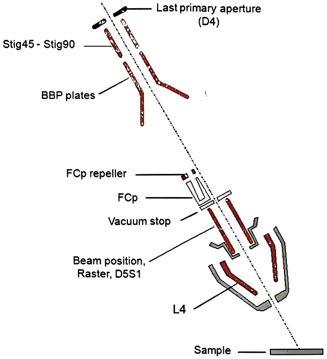
1.1.4 Primary beam impact angle and the landing issue
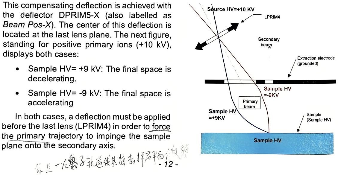
Section titled “1.1.4 Primary beam impact angle and the landing issue”All the space located between the source and the extraction electrode is at the ground potential except the space located between the extraction electrode and the sample plane. This space is an accelerating region for the secondary ions, while, for the primary ions, it is a decelerating space if both the primary and secondary voltage have the same polarity and it is an accelerating space if they have opposite polarities. As the primary axis is not normal to the sample plane, the primary trajectory is curved in this region, and it would not impinge the sample plane onto the secondary axis if there was not a compensating deflection depending on the decelerating or accelerating field.
This compensating deflection is achieved with the deflector DPRIM5-X (also labelled as Beam Pos-X). The center of this deflection is located at the last lens plane. The next figure, standing for positive primary ions (+10 kV), displays both cases:
- Sample HV= +9 kV: The final space is decelerating.
- Sample HV= -9 kV: The final space is accelerating
In both cases, a deflection must be applied before the last lens (LPRIM4) in order to force the primary trajectory to impinge the sample plane onto the secondary axis.