2.2 High voltage and real time cabinet starting
2.2.1 Cabinets and communications starting
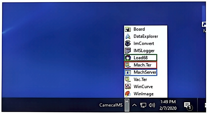
Section titled “2.2.1 Cabinets and communications starting”- Open the Mach.Ter window on the instrument PC (red box in the figure below). A blank window appears, do nothing in this step).
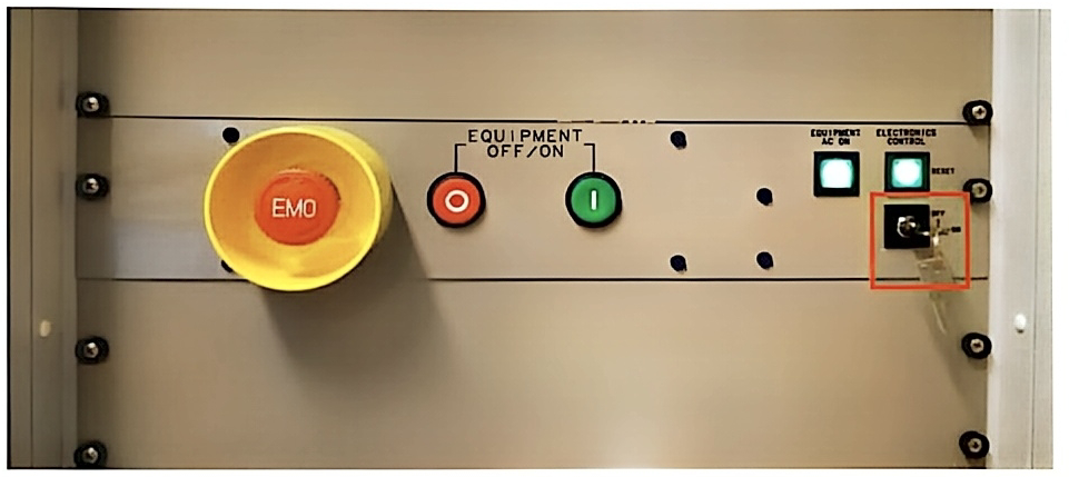
- Turn the key located on the front of the Vacuum rack and called “Electronics control” to ON.
- Check that all chassis and power supply at the rear of the two cabinets are turned on.
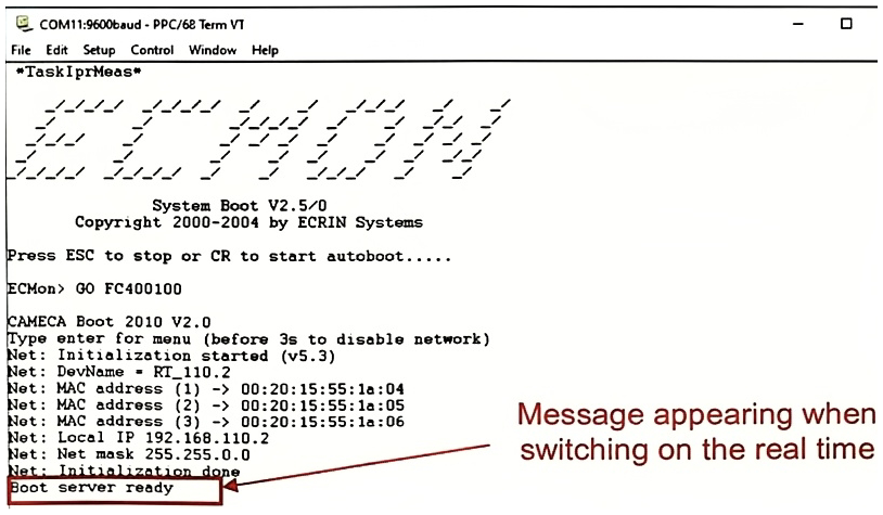
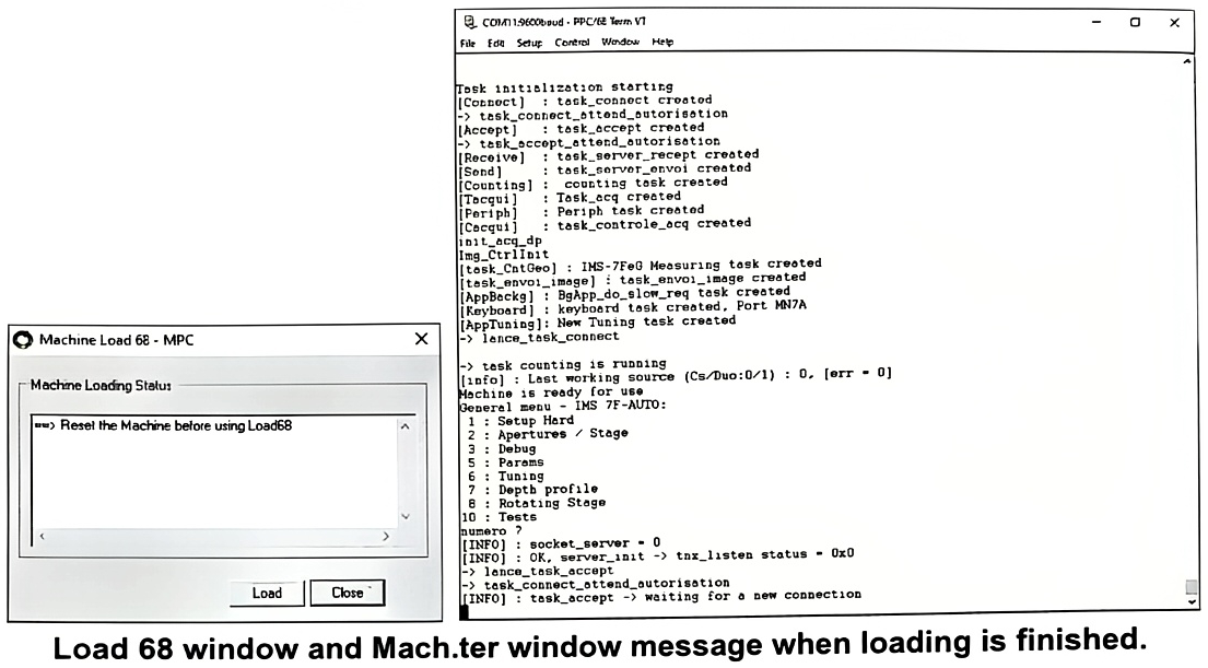
- When starting the real time chassis, the message “Boot server Ready” should appear in the Mach. Ter window like in the figure below.
- Open the “Load 68” window (green box on Cameca ims taskbar figure above) and click on “Load” to load the 7FAUTO parameters in real time. The loading is finished when the message “task_accept → waiting for a new connection” appears in the Mach.Ter window
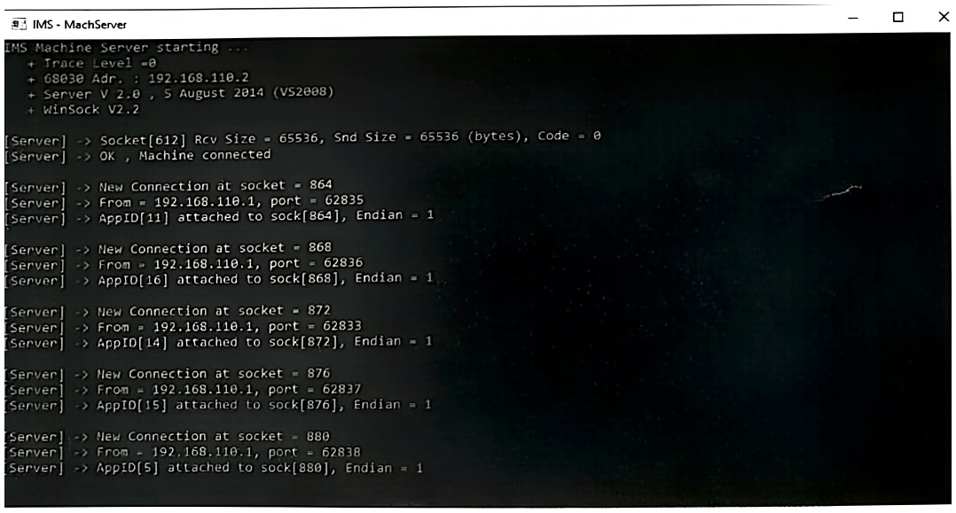
- Open the MachServer window (blue box on Cameca ims taskbar figure above) to establish the connection between the instrument PC and the real time PC.
Note that these operations must be carried out each time the electronics are restarted, or the Real Time is Reset.
If one chassis is switched off, when it is switched on back, it is necessary to connect it to the real time. The step to connect individually a chassis is shown below:
-
Switch on the chassis
-
In the Mach.Ter window, go to the “Param” submenu by entering the number 5 in the root menu.
-
Here the list of the name of each chassis in the Mach.Ter program :
-
sims_fast_bac_duo (for Duo source chassis)
-
cs (for Cesium source chassis)
-
ims7f_fast_bac_i (for Coils/low voltage chassis)
-
ims7f-fast_bac_ht_1 (for High Voltage Rack 1 chassis)
-
ims7f-fast_bac_ht_2 (for High Voltage Rack 2 chassis)
-
ims7f-fast_bac_ht_3 (for High Voltage 3 Rack chassis)
-
sec_hv_3 (for Post acceleration Chassis)
-
eg (for Electron gun chassis)
-
motor (for Motor chassis)
Then type ““name of the chassis” connect” in the window. This command allows the real time chassis to communicate with the chassis.
When a chassis cannot connect to the Real Time (wiring, board connection, problem with internal RS485 components, etc.), the message “Not Available” is displayed next to the name of the chassis.
2.2.2 Motors initialization
Section titled “2.2.2 Motors initialization”After cabinets and communications starting, the motors must be initialized. Here the steps to do it:
- Initializing the apertures and Slit motors:
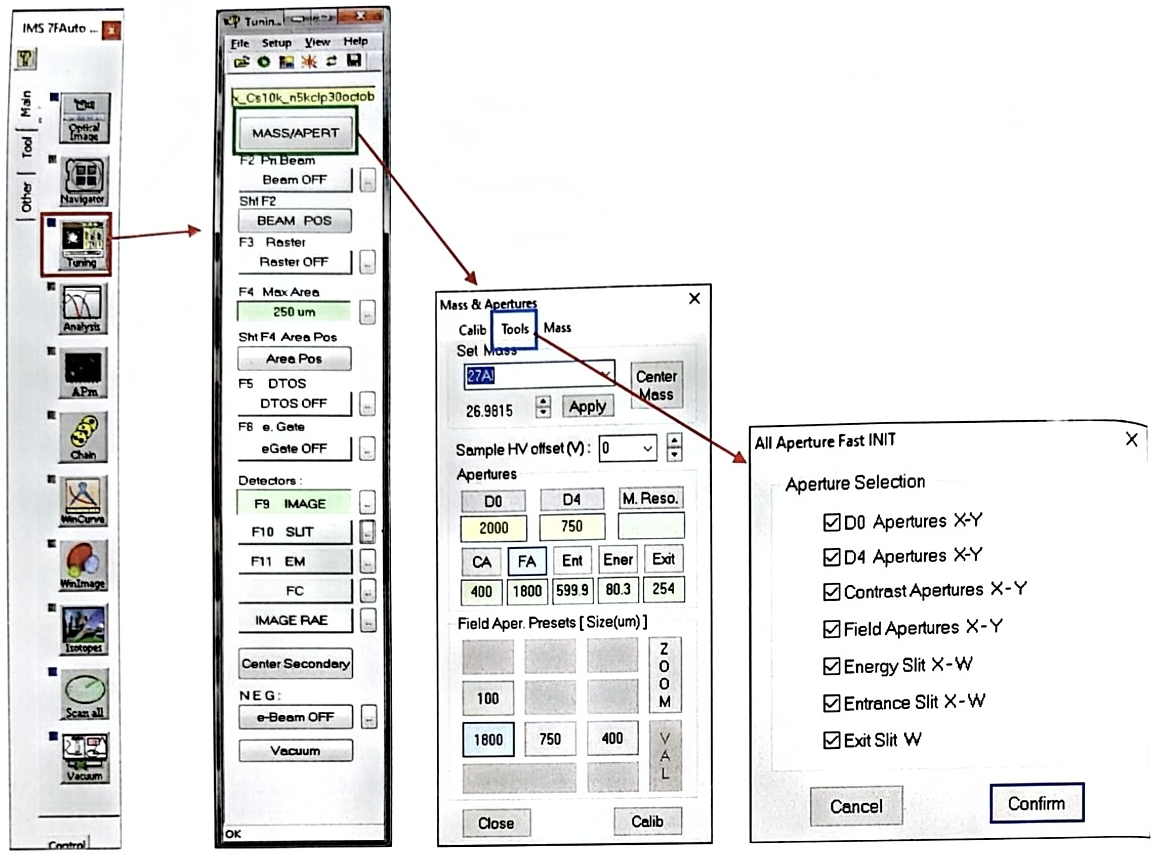
In the Board window, open Tuning window (Red box in the figure below) and click on MASS/APERT button (green box in the figure below). A window “Mass & Apertures” open. Click on Tools in the menu (blue box in the figure below) and click on “Apertures init”. The window “All Apertures Fast Init” appears, check all the boxes and click on Confirm. All the Apertures and Slit motors will be initialized.
- Initializing the stage motors:
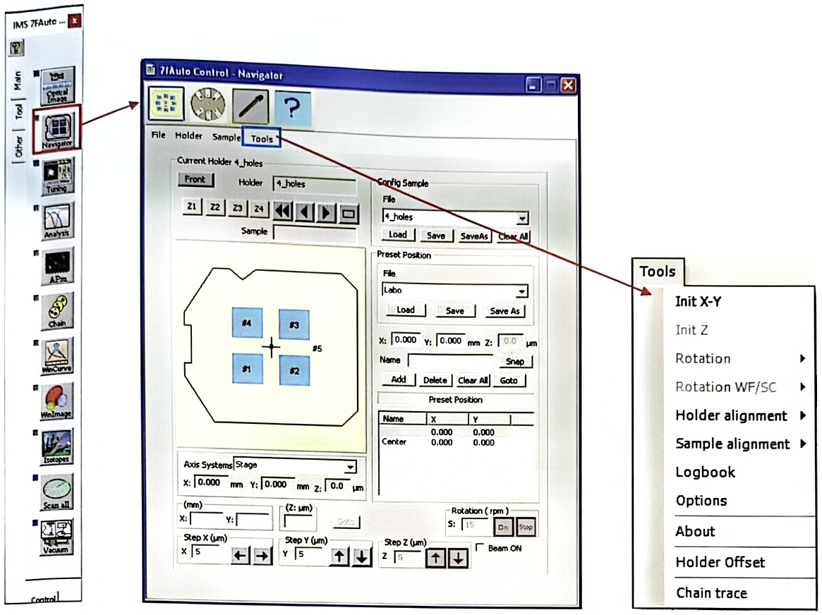
In the Board window, open Navigator window (Red box in the figure below). Then click on Tools in the menu (Blue box in the figure below) and click finally on “Init X-Y”. The stage motors will be initialized.