2.1 Vacuum cabinet starting
- Switch on the three main circuit breakers on the terminal block (back of the vacuum cabinet) and check whether the “Power” LED turns green on the front panel of the mains filter.
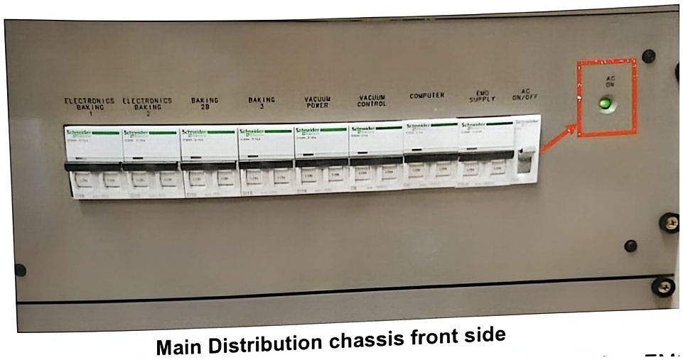
- Switch on the “AC” circuit breaker (Red box in figure below) located on the front of the Main Distribution chassis and verify that the “AC ON” LED next to it is green. Switch on all the breakers on the main distribution chassis then.
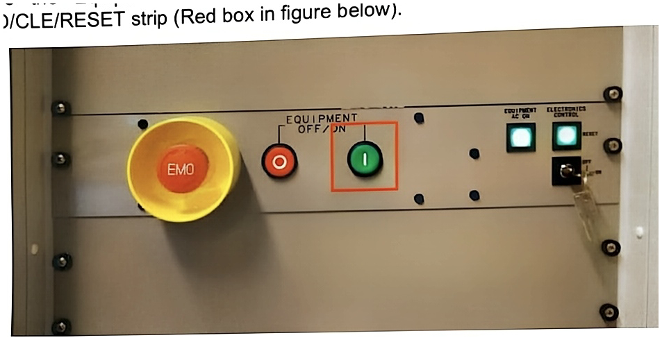
- Press the Equipment ON/OFF green button located next to the EMO on the EMO/CLE/RESET strip (Red box in figure below).
- Check that all chassis and pump power supply inside cabinet are individually turned on.
- On the computer, open the Vac.Ter vacuum control window located in the CamecaIMS taskbar (red box in figure below). This control window provides access to the settings associated with the vacuum. However, you must pay attention to the commands entered in this window because there is no security when the actions are performed (risk of general ventilation of the instrument, etc.).

- Then open the vacuum synoptic. This window provides an overview of the pressures in each part of the instrument and allows you to control the valves, turbo pumps and gauges. To open it, right-click on “Board” to open it as an administrator in the CamecaIMS menu bar (green box in figure above)
- On the Board, then click on “Vacuum” (Red box in figure below). The vacuum synoptic window then appears (figure below on the right). When the synoptic is open, a “Vac server” window also appears. Do not close it. Also verify that the communication is correct (green COM indicator pointed with the red box in the figure below).
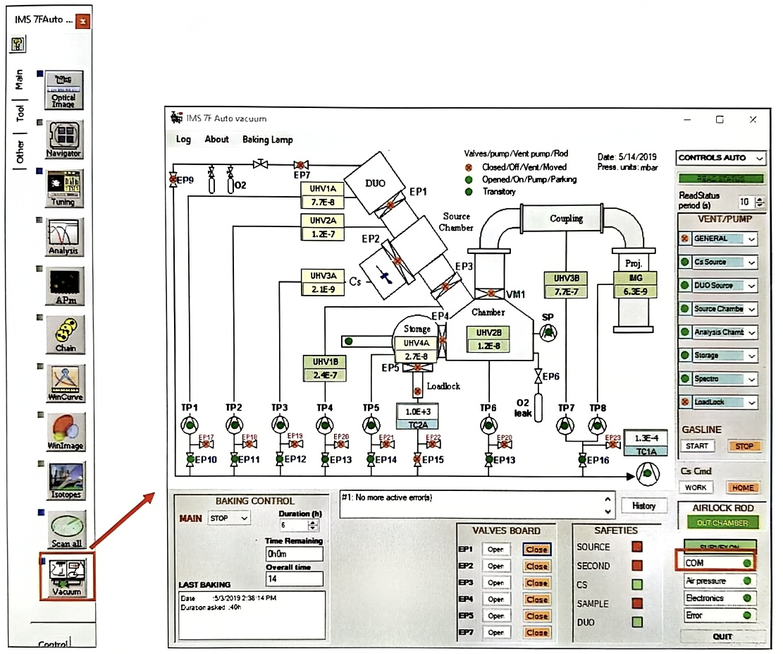
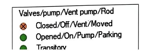
The different valves are represented on the vacuum synoptic by the following graphic elements:
- EP10 : Valves bringing the primary pumping to the different parts of the instrument (EP9, EP10, EP11, EP12, EP13, EP14, EP15, EP16)
- Valves supplying nitrogen to the pumps (machine ventilation, pump slowing) (EP17, EP18, EP19, EP20, EP21, EP22, EP23). EP7 brings oxygen to the Duoplasmatron source.
- VM1 : Valves located on the body of the instrument (VM1, EP1, EP2, EP3, EP4)
Their status is characterized in the vacuum synoptic by indicators of different colors shown in figure below (the “Transitory” status is characterized by green and red flashing):
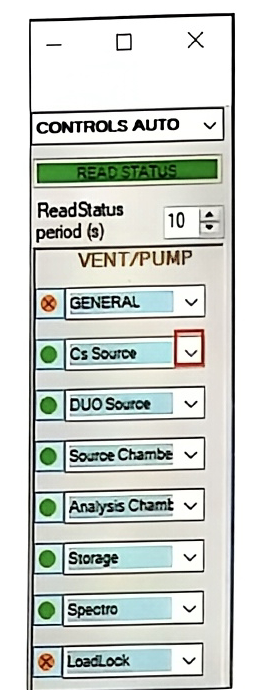
- On the vacuum synoptic on the right, the state of each part of the instrument is indicated: vented (red) or pumped (green) or in a transitory state (flashing). Before pumping or venting, please be sure that the valve related to this part are closed, a message will remind you and the process of venting or pumping will be canceled is the valves are not closed. To pump or vent, click on the arrow (red box on the figure below) next to the name of the part and click on the state you want to apply. When the machine is fully vented, each part of the instrument has to be pump individually and only one part can be pump at the same time.