1.2 Mass spectrometer and Secondary column
The IMS-7f-Auto mass spectrometer consists of:
- The matching transfer optics consisting of a set of lenses purposed to “match” the emitted secondary beam to the mass spectrometer, i.e., to fill properly both mass spectrometer entrance apertures, the Entrance Slit and the Field Aperture.
- The double focusing mass spectrometer, basically consists of a magnet, dispersing two different ion mass trajectories, and an electrostatic sector (ESA), cancelling the magnet energy dispersion which is a counterpart of the mass dispersion. In combination with the magnet, an Exit Slit allows to filter a narrow mass band [M-ΔM/2, M+ΔM/2]
- The ion counting detection system, located just after the Exit Slit, and consisting of an electron multiplier (EM) and a Faraday cup (FCs).
- The projection ion optics also located just after the Exit Slit, and used alternatively with the ion counting detection system, purposed for projecting either the ion sample image or the Exit Slit plane image onto a microchannel plate device (MCP). A CCD camera allows to display these images on a video monitor.
The secondary ion optics can be considered as a mass filtered ion microscope since the sample plane image is transferred all along the secondary optics and can finally be displayed in the MCP plane.
The secondary ion optics can also be considered as the detection device of a Scanning Ion Microscope (SIM) since a so-called dynamic transfer (DT) deflection device, synchronized with the primary raster signal allows to collect the secondary ions from a sputtered area as large as 500 × 500 μm .
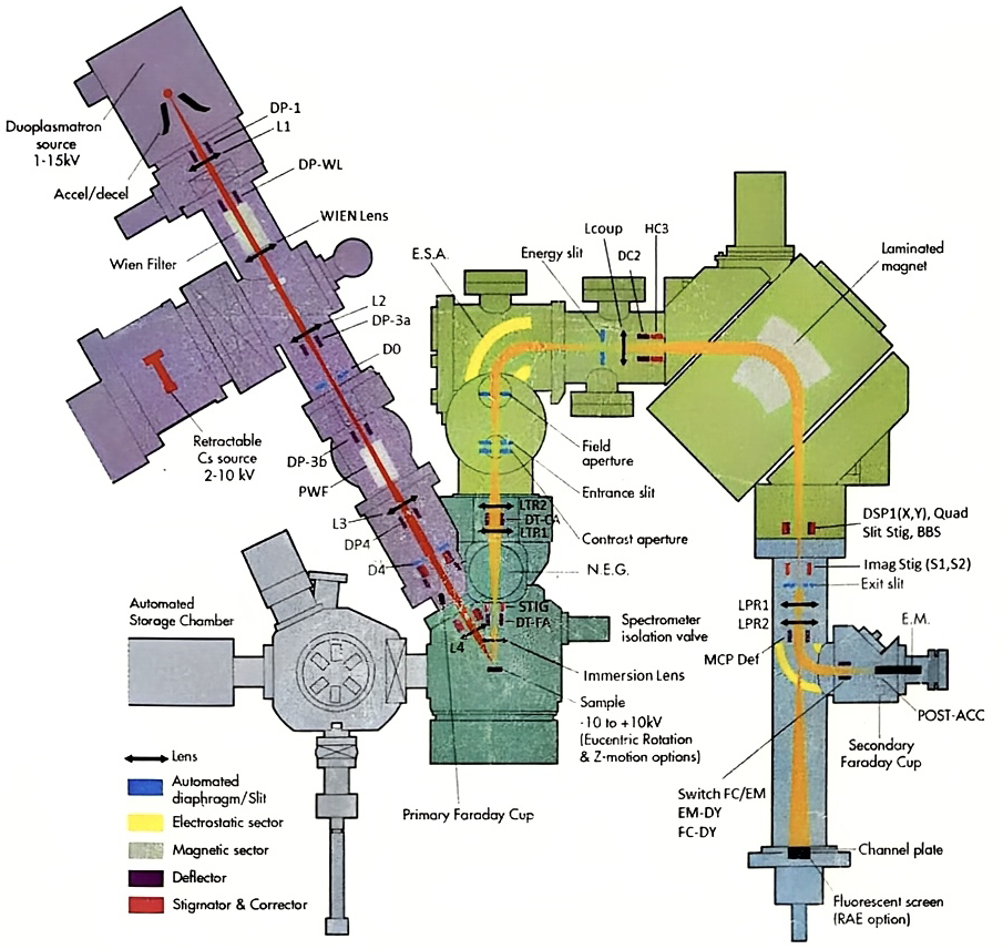
| Device Label | Functional Labels | Functionality |
| Sample stage | SAMPLE HV | Sample stage biased at High Voltage (Sample HV). Both the Last Lens last electrode and the immersion lens first electrode are also biased at Sample HV. |
| Immersion Lens | LIMM | Electrostatic immersion lens consisting of the acceleration space comprised between the sample plane connected to secondary HV and the front grounded plate and a conventional einzel lens the external electrodes of which are grounded. It plays both roles of secondary ion acceleration and ion microscope objective lens. |
| Dynamic transfer DT1 | DT-FA DT-FA DT Raster X DT Raster Y | This device consisting of two pairs of deflection plates is approximatively located at the immersion lens pupil plane.A fast Raster signal synchronized with the primary raster can be driven on the device. In addition to the fast Raster signal, a static centering is also implemented onto this device. Dynamic or static deflection move the beam in the Field Aperture plane. |
| Stigmator ST2 | STIG X STIG Y | 8 pole devices controlled as a stigmator. |
| Transfer lens LTR1 | LTR1 | Electrostatic lens forming the matching transfer optics in combination with the immersion lens LIMM and LTR2. |
| Deflector DT3 | DT CA X DT CA Y | This device consisting of two pairs of deflection plates is located between transfer lenses LTR1 and LTR2. It is purposed to align the beam with respect to the contrast aperture CA. |
| Transfer lens LTR2 | LTR2 | Electrostatic lens forming the matching transfer optics in combination with the immersion lens LIMM and LTR1. |
| Contrast Aperture CA | CA X CA Y | One among 4 stops located on a movable bar can be selected and centered onto the secondary axis. Normal diameters are 400μm, 150μm, 50μm and 20μm. The smaller the diameter the better the lateral resolution of the sample surface image in the microscope mode.The bar is driven by 2 stepping motors (X & Y). The 4 stops are placed along the Y axis. |
| Entrance Slit | ENT SL X ENT SL W | Slit width vary from 0 to 1500μm. It is driven by 2 stepping motors, for the X centering and for the W adjustment. A small width is required for a high mass resolution. |
| Field Aperture | FA X FA Y | One among 4 stops located on a movable bar can be selected and positioned on the secondary axis. Normal diameters are 1800μm, 750μm, 400μm and 100μm. A small diameter is required for a high mass resolution. The bar is driven by 2 stepping motors (X & Y). The 4 stops are placed along the Y axis. |
| Spectro ESA | ESA1 | Spherical electrostatic sector. Its radius is 85 mm. Controlled by a single variable which is the average between the absolute value of its 2 electrode voltages. Forms the image of the Entrance Slit in the Energy Slit plane. |
| Energy Slit | ENER SL X ENER SL W | Aperture consisting of 2 movable edges LE (Low Energy) and HE (High Energy). The motion axis is Ox. Both edges are controlled by variables X and W:LE Position = XHE Position = X + W |
| Coupling Lens | LCOUP | Electrostatic lens purposed for achieving the spectrometer achromatism in combination with the ESA and the Magnet. |
| Deflector DC2 | DC2 Y | Deflector used to center the beam within the magnet tube. |
| Hexapole HC3 | HC3 | Hexapole tuned for minimizing the spectrometer second order aberrations. |
| Magnet | Mass | Magnet controlled directly from the operator keyboard. |
| Quadrupole | DPR X DPR Y QUAD BBS DEF | 4 plate multipoles with 4 implemented functions:• A Beam centering in X and Y• An X/Y stigmator• A fast beam-blanking BBS |
| Image Stigmator | STIG X STIG Y | 8 poles stigmator used for improving the sample image (in the projection image mode) and for adjusting the parallelism of the entrance slit image with respect to the exit slit. |
| Exit Slit | EXIT SL W | Exit slit width vary from 0 to 1500μm. It is driven by one stepper motor for the W adjustment and one for The X centering. A small width is required for a high mass resolution. |
| Proj Lens LPR1 | LPR1 | Electrostatic lens. In combination with LPR2, it forms the projection zoom, allowing to project onto the MCP plane either an ion image of the sample plane or an ionic image of the beam section at the exit slit plane. |
| Proj Lens LPR2 | LPR2 | Electrostatic lens. In combination with LPR1, it forms the projection zoom, (See above, LPR1). |
| MCP deflector | D MCP X D MCP Y | 4 plate deflectors used for centering the beam within the MCP. |
| Exit ESA | EXIT ESA | Spherical Electrostatic sector. When biased, it switches the ion beam toward the detection stage. When not biased, a hole allows the beam to go straight forward to the MCP plane. |
| Switch FC/EM | EM-DY FC-DY | 2 plate deflectors located just after the exit ESA, allowing to switch the beam either into the Faraday cup, or onto the EM first dynode. As the EM is on-axis, the voltage corresponding to the EM is close to zero. |
| EM | EM HV EM THRES PA HV | Electron Multiplier used for ion counting |
| FCs | FDY RPL | Faraday cup is used for measuring the secondary ion current in the Faraday mode, i.e., directly. The Faraday Repeller (FDY RPL) is a plate located just before the Faraday cup for repelling the secondary electrons generated by the secondary ion impact in the Faraday cup. |
| MCP | MCP CP SCINT | Ion image intensifier consisting of a Micro Channel Plate and a Phosphorus screen. |
1.2.1 The Immersion lens
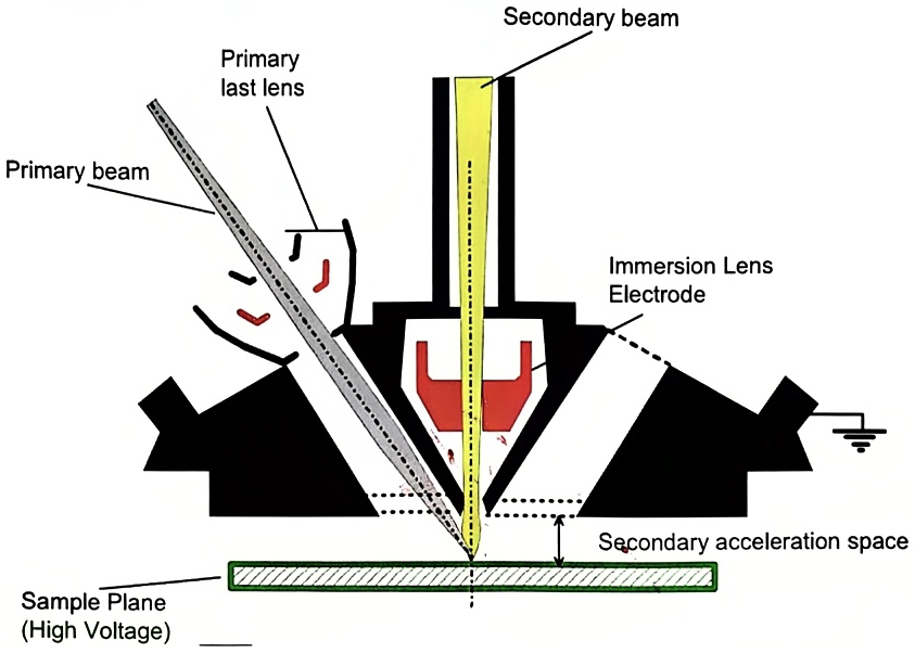
Section titled “1.2.1 The Immersion lens”The immersion lens is the objective of the matching transfer optics. As it can be read in the User’s guide: Basic Ion Optics, Electrostatic Lenses, the immersion lens is formed by all the spaces between the sample and the last grounded electrode.
A schematic of the immersion lens region is displayed in the figure below. As it can be seen, the part of the primary trajectory located just before the sample is strongly immersed in the secondary extraction field.
1.2.2 The trajectories in the immersion lens region, the cross-over
Section titled “1.2.2 The trajectories in the immersion lens region, the cross-over”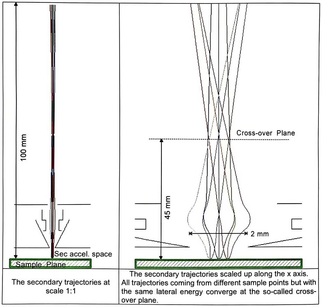
1.2.3 The matching transfer ion optics
Section titled “1.2.3 The matching transfer ion optics”The secondary SIMS ion source can be featured as an emitting area at the sample plane and an angular emitting diagram. The emitting area is mainly determined by the primary ion probe, while its intensity and its angular diagram is mainly determined by SIMS processes.
A mass spectrometer entrance consists of a pair of apertures, the Entrance Slit, which limits the beam area, and the Field Aperture (FA), which limits its angular aperture.
The so-called Matching Transfer ion optics system is a set of 3 lenses, the immersion lens and two other transfer lenses (LTR1 and LTR2). This ion optics system is purposed to match the secondary ion source to the mass spectrometer entrance.
Coarsely, the matching transfer ion optics of the IMS 7f-Auto produces a sample image within the Field Aperture plane, while the angular diagram is imaged at the Entrance Slit plane, or more precisely, a lateral energy diagram is formed at the entrance slit plane. This region of the beam imaged at the entrance slit plane is so-called the “Cross-over” since it corresponds to the smallest beam cross-section.
Additionally, to the entrance slit and the field aperture, another aperture located very close to the entrance slit, the so-called Contrast Aperture (CA) is used for limiting the lateral energy in order to get a better lateral resolution when forming the sample image in the ion microscope mode. 4 different diameter apertures can be selected: 400 μ m, 150 μ m, 50 μ m and 20 μ m. The effect of this CA is to limit the immersion lens aberrations.
Practically the user must select a sample image magnification. It must be clear that the respective magnifications of both the sample image and the cross-over are balanced: Increasing the sample image size leads to decrease the cross-over diameter. According to each specific application, the zoom selection will be achieved with respect to the following considerations:
- Optical gating: The field aperture is then used for selecting in the sample image a limited area to be analyzed.
- Transmission optimization: Both the FA and the Entrance Slit are determined for a given mass resolution. At a given mass resolution, if the beam cross section within the FA (i.e. the sample image) is smaller than the FA, it is then recommended to set the transfer zoom in order to fully fill the FA with the beam and to reduce therefore its diameter within the entrance slit which will be better in terms of transmission.
1.2.4 The trajectories in the transfer ion optics:
Section titled “1.2.4 The trajectories in the transfer ion optics:”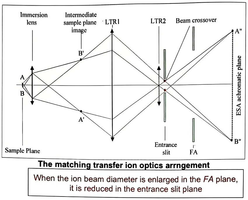
1.2.5 Mass dispersion and Energy focusing principle
Section titled “1.2.5 Mass dispersion and Energy focusing principle”The double focusing mass spectrometer includes first a magnet which produces the magnetic field required for dispersing the beam in mass.
The secondary ion energy spread can be as large as several tens of eV. If the spectrometer were consisting of a single magnet, a mass spectrum peak would be completely blurred by this energy dispersion, leading to a very poor mass resolution. Compensating the magnet energy dispersion by an electric field produced by an electrostatic sector analyser (ESA) is the basic principle of a double focusing spectrometer.
For achieving the cancellation of the energy dispersion, an electrostatic lens, called coupling lens or spectrometer lens is added between the ESA and the magnet. The figure below of this section shows how the energy focusing is obtained with this arrangement: The 3 trajectories (yellow, red and blue) correspond to 3 different energies. They are primarily dispersed by the ESA. The electrostatic lens then inverts their dispersion angle, so that the magnet energy dispersion cancels completely the ESA dispersion.
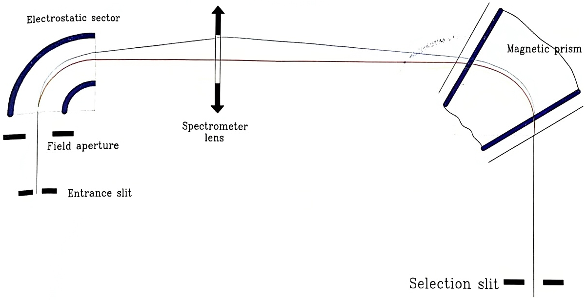
The double focusing spectrometer produces the entrance slit image in the exit slit plane, at scale 1.5:1 and the sample image approximatively at the magnet center plane