8.3 Alignment procedure for Immersion lens and Transfer
8.3.1 Instrument conditions
Section titled “8.3.1 Instrument conditions”Instrument conditions: FA #1 (1800μm), CA #1 (400μm), Max area (Transfer preset) 250 μm, Entrance Slit full open (400μm) and Exit Slit full open (1200 μm).
8.3.2 Alignment procedure
Section titled “8.3.2 Alignment procedure”Setting the DT-CA(X,Y) and CA position
The goal of ‘Transfer alignment’ is to maximize the transmission from the sample surface through the Immersion lens, Transfer lenses (LTR1 & LTR2) up to the entrance of ESA. Following procedure is aimed at finding and optimizing DT-CA (X,Y) values and CA (X,Y) position.
-
Set the Immersion lens value to >90% of the sample HV ( >4500 V if the sample HV is set to 5000 V ). Set LTR1, LTR2 to 0.
-
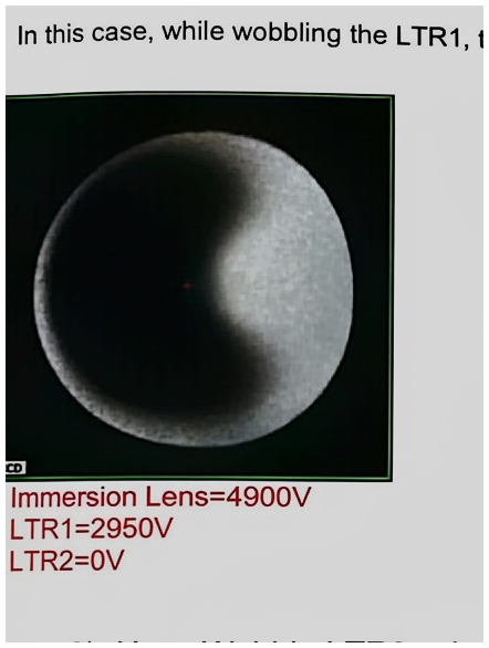
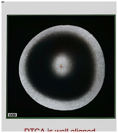
Wobble LTR1 value, then center the beam spot using DT-CA X and Y to keep the focal point, then reset LTR1 to 0. Please take a note your DT-CA value on a notebook.
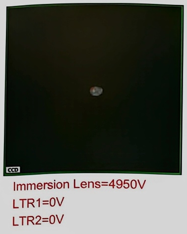
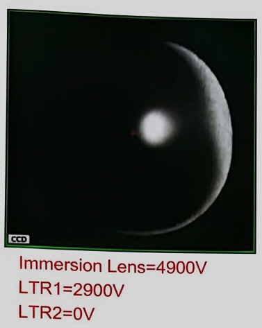
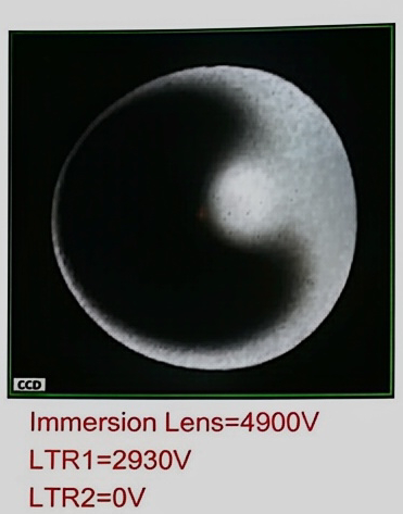
In this case, while wobbling the LTR1, the center of beam is changing => DTCA value is not correct.

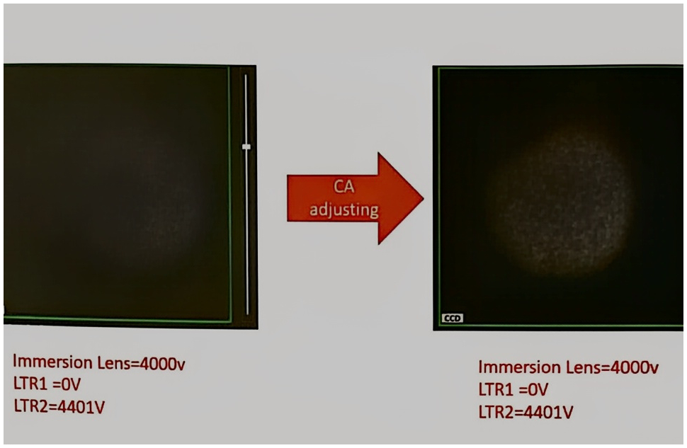
- Now, Wobble LTR2 value while keeping LPR1=0, then center the beam spot using CA X & Y to keep the focal point, then reset LTR2 to 0.
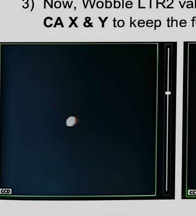
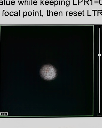
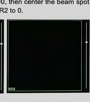
In this case, while wobbling the LTR2, the centre of beam is changing. => CA value is not correct.
-
Repeat two last steps (2 & 3) until the two lenses LTR1 and LTR2 are correctly centered together.
-
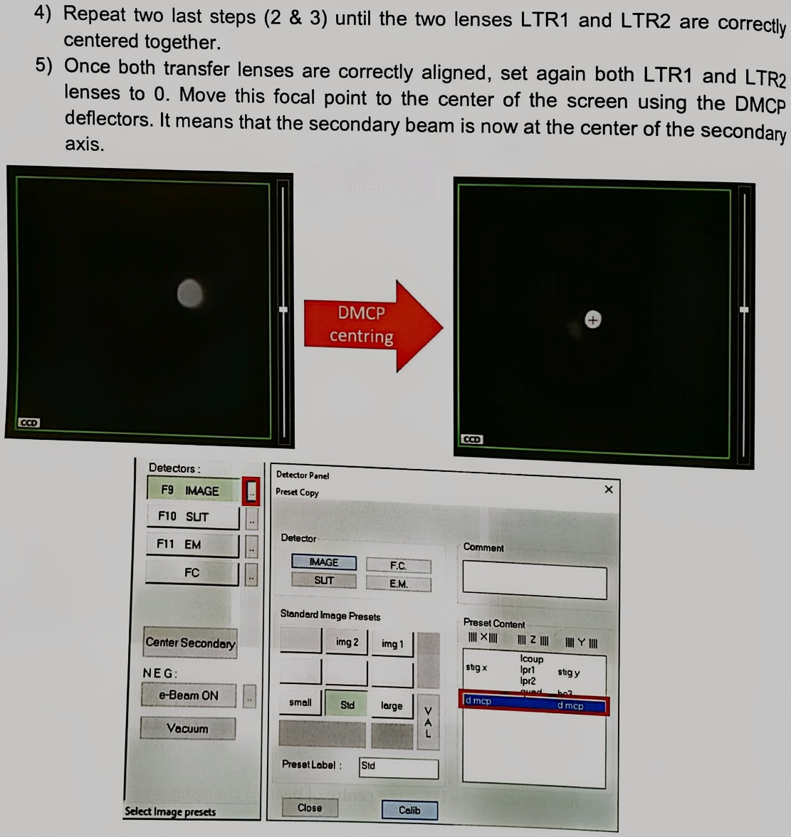
Once both transfer lenses are correctly aligned, set again both LTR1 and LTR2 lenses to 0. Move this focal point to the center of the screen using the DMCP deflectors. It means that the secondary beam is now at the center of the secondary axis.
-
As you obtained correct values for both DT-CA(X,Y) and CA (X,Y) position, validate first ‘CA’ preset of ‘Mass & Apertures’ panel.
-
Then recall (by clicking) the Max area preset without any change. All parameters must be the same as before alignment. Now, set DT-CA (X,Y) values written on your notebook during the procedure 2) above. Then, validate ‘Max area’ preset.
Setting the FA position
Section titled “Setting the FA position”-
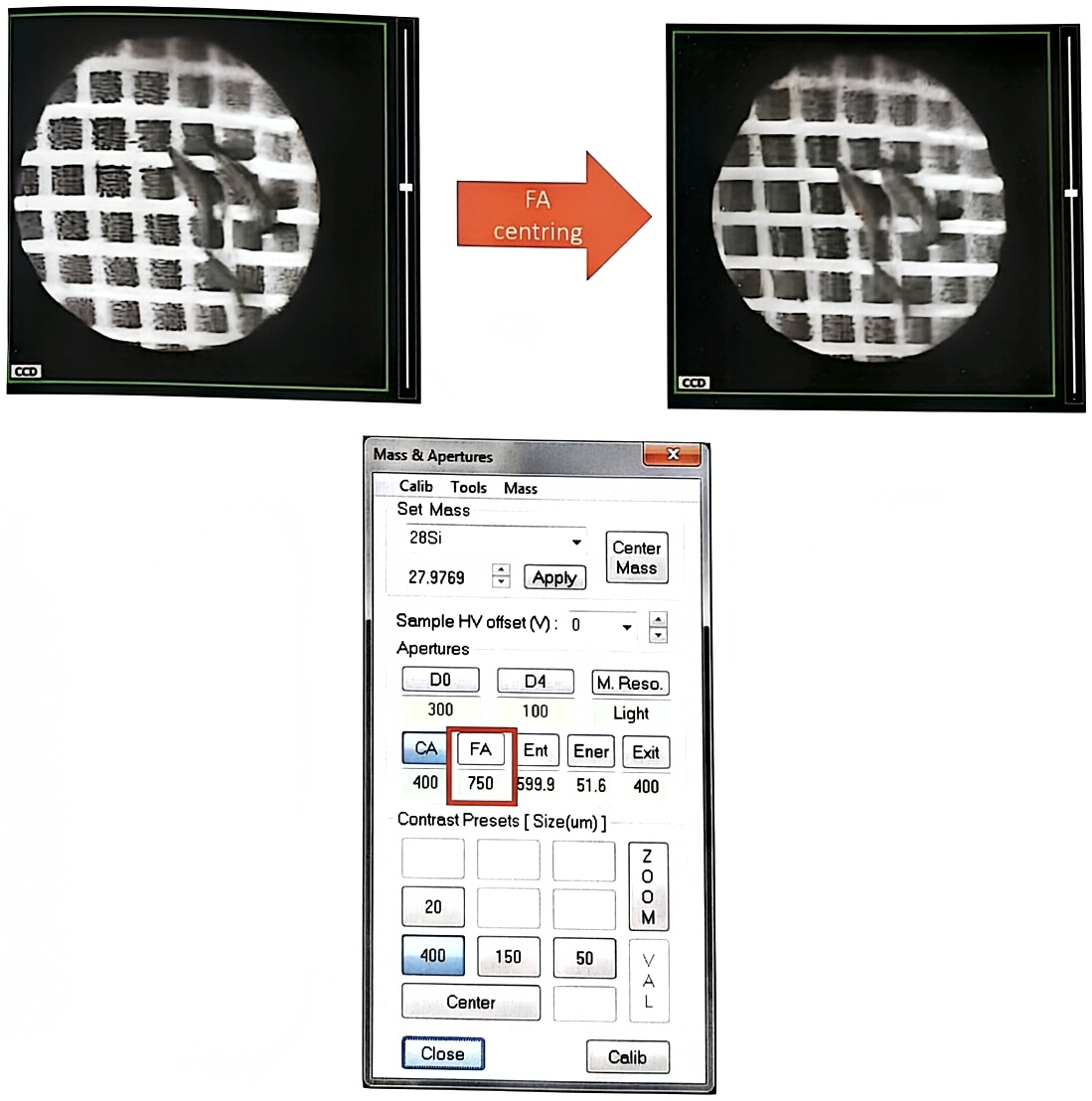
Turn on rastering of the primary beam on the sample surface (200 ~ 250 μ m). The position of FA is probably off the center. Select ‘FA’ preset of ‘Mass & Apertures’ panel, and center FA position at the center of the Micro Channel Plate.
-
Recheck that all new values are validated: CA & FA position,-Max Area preset with your new DTCA value.
Setting different Max ares presets
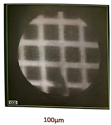
Section titled “Setting different Max ares presets”For other ‘Max area’ presets, adjust the LTR1/LTR2 values to get a new image with the field of view desired. (100μm for 4 grids; 150μm for 6 grids; 250μm for 10 grids)
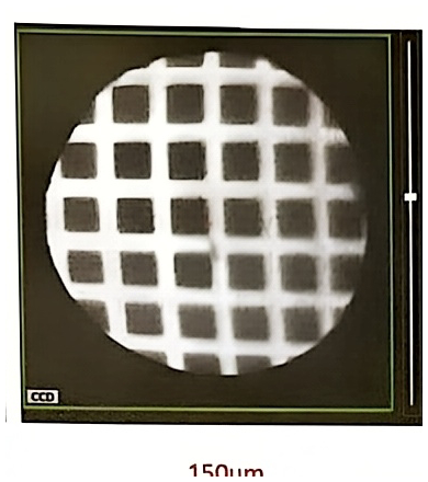
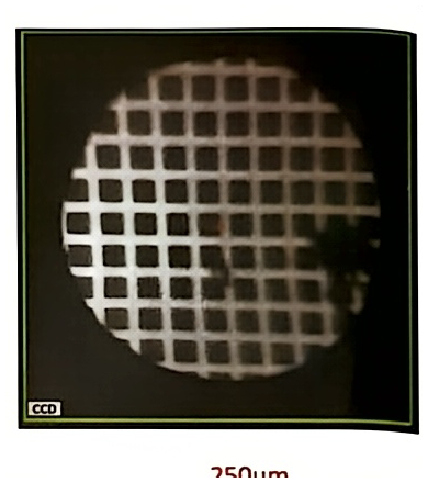
Note: Cycle all the steps, from projection to the transfer until the secondary column is perfectly aligned.