1.3 The Visualization / Detection system
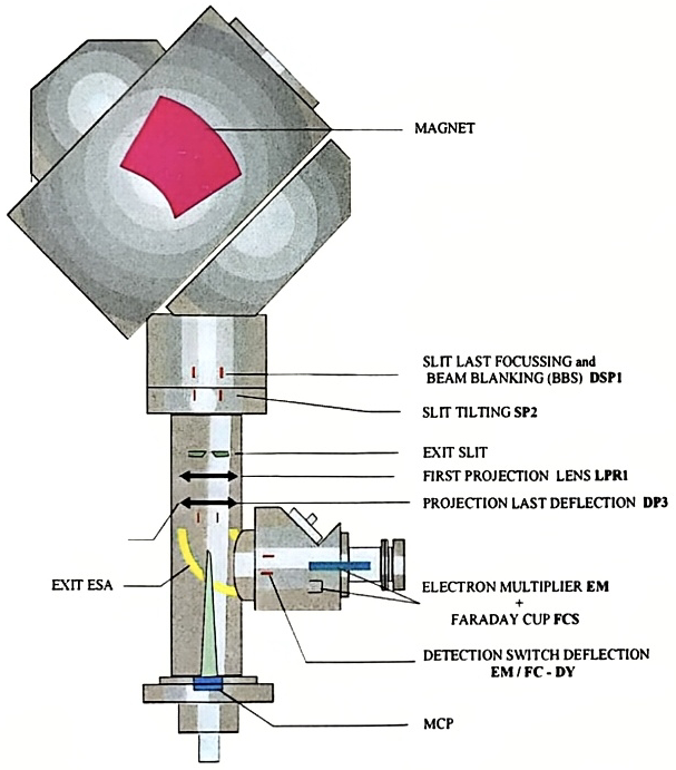
The detection system consists of a spherical ESA which allows to switch the secondary beam towards the secondary detectors. A hole located in the external electrode allows the ions to pass through this Exit ESA when it is set to OFF.
Just after the Exit ESA, a deflector allows to deflect the beam either towards an EM device or towards a Faraday cup device.
1.3.1 The MCP direct imaging
Section titled “1.3.1 The MCP direct imaging”A pair of lenses, LPR1 and LPR2 (called projection lenses) are purposed for projecting onto a MicroChannel Plate (MCP) either an ion sample image or the beam cross section as it is at the exit slit plane.
Image mode corresponds to the first case (sample imaging). This mode is also referred as Ion Microscope Mode.
Slit mode corresponds to the second case (exit slit plane imaging).
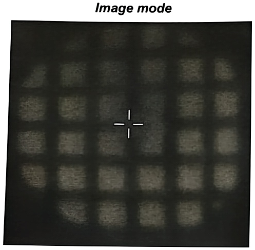
A Si grid sample projected onto the MCP in the image mode
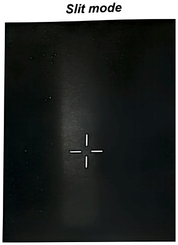
Entrance Slit image projected onto the MCP in the slit mode.
1.3.2 MicroChannel plate/ Fluorescent screen (MCP/FS)
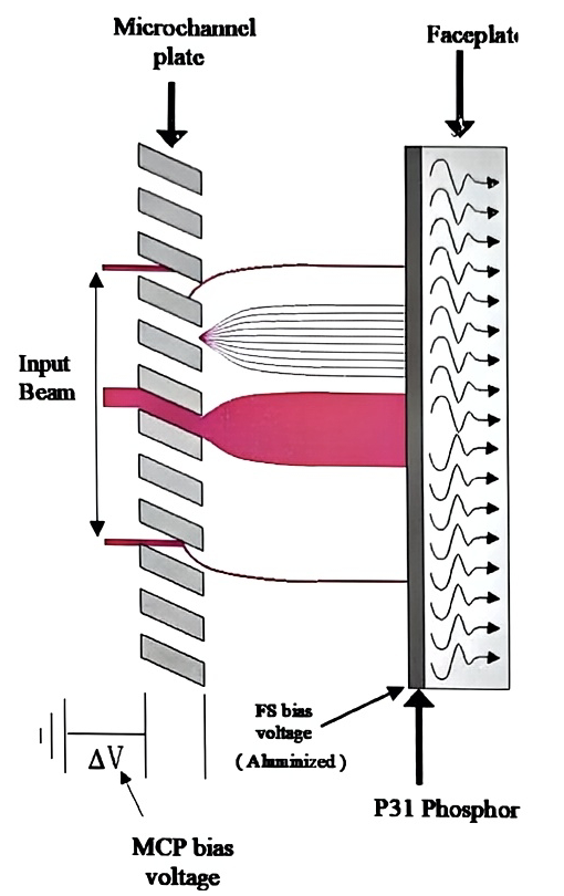
Section titled “1.3.2 MicroChannel plate/ Fluorescent screen (MCP/FS)”This system consists of a microchannel plate device coupled to a fluorescent screen. The microchannel plate converts secondary ions in electrons, the fluorescent screen converts electrons in photons. The fluorescent screen image is acquired by the means of a CCD camera and displayed on the real time screen.
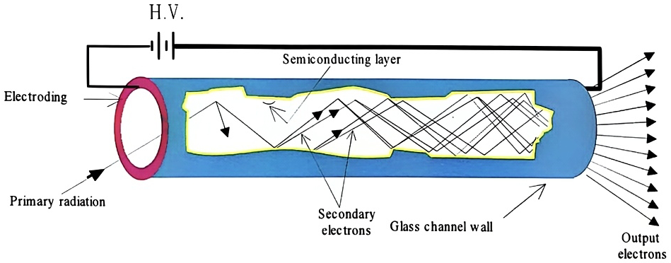
A MCP is an assembly of small channels ( ∅ ≈ 10 μm ). Each channel is a small hollow glass tube with the inner surface covered by a SiO2 emissive layer (or a conductive layer) compounds. When a secondary ion strikes the semiconductor surface, there is secondary electron emission, these electrons are accelerated and multiplied by collision cascades in the channel. The useful surface of the MCP device (open area/total area ratio is more than 50 %).
The MCP gain (number of secondary electrons produced per secondary ion) is adjustable (typically from a few 10² to 10⁴ ) by controlling of the potential applied across the detector. This potential can vary from 400 V to 1500 V. The higher the potential the higher the gain. The fluorescent screen is brought at potential which is automatically adjusted in order to keep a constant extraction voltage of 5000 V for the electrons which focuses the e⁻ in a spot of about 70 μm in diameter onto the screen. The adjustable gain of the MCP/FS image detector offers the capability of imaging over a very wide dynamic range.
The MCP/FS system is schematically represented on the hereunder figures.
1.3.3 Ion detectors for counting mode
Section titled “1.3.3 Ion detectors for counting mode”The IMS 7f and 4fE7 are equipped with two types of ion detectors for the counting mode: one Faraday cup (FCs) and one electron multiplier (EM). The combination of both Faraday cup and electron multiplier provides a very high dynamic range for the secondary intensity measurements.
The Faraday cup (FCs) and electron multiplier (EM) are used to measure count rates in the range [5 × 10⁵; 5 × 10⁹] and [10⁻¹; 10⁶] c/s, respectively. The overlap of the intensity ranges allows to combine both detectors within a given analysis. The two detectors are mounted side by side on the secondary beam trajectory after the second electrostatic analyzer of the instrument (projection part). The deflector located in front of the detector assembly is used to apply a fast switch of the secondary beam from one detector to the other.
1.3.4 Faraday cup (FCs)
Section titled “1.3.4 Faraday cup (FCs)”The Faraday cup is a hollow cylinder with large ratio length/diameter isolated from the instrument ground. In order to measure accurate secondary ion intensities, it is mandatory to prevent the secondary electrons induced by the ion bombardment of the Faraday cup walls from escaping of the Faraday cup. This is achieved by placing a repeller (a plate negatively biased) in front of the Faraday cup.
A schematic drawing of the IMS Faraday cup system is shown in the here under figure:
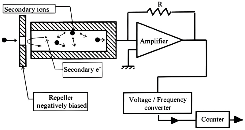
The charges brought by the secondary beam focused into the Faraday cup produces a current which is converted into a voltage by a high impedance amplifier. This voltage is sent at the input of a voltage/frequency converter.
1.3.5 Electron multiplier (EM)
Section titled “1.3.5 Electron multiplier (EM)”The IMS 7f-Auto is equipped with an electron multiplier (EM) working in a direct pulse counting mode. The most used EM is manufactured by ETP. It is made of 21 active film dynodes.
A secondary ion striking the first dynode (conversion dynode) of the EM induces a secondary electron emission. Then, these electrons are accelerated through the successive dynode stages to amplify the secondary electron current. A gain (mean number of electrons per secondary ions) of about 10⁸ is obtained. For most of the secondary ions reaching the detector, a charge pulse is produced at the last dynode output. The charge amplitude is converted in voltage, and the pulse amplitude, in Volt is proportional to the EM gain. Note that some incident ions do not produce any signal at the EM output.

The amplitude of every pulse is randomly distributed according to a distribution law currently displayed by the PHA Distribution Curve (PHA states for Pulse Height Amplitude). The knowledge of this distribution is therefore very helpful to optimize the setting of the EM High Voltage (HV), and Threshold. Checking this curve shape also used for controlling the EM aging.