9.3 Alignment Procedure:
STEP A: Centering of the Cs source position
Section titled “STEP A: Centering of the Cs source position”-
Apply the starting conditions described above, if not yet done.
-
Keeping Beam OFF, maximize the primary current using DP_3a (X, Y).
-
If Cs source is well centered on the primary column axis, the maximum primary current is achieved with very low DP_3a (X, Y) values which are closed to zero.
- If DP_3a (X, Y) values are lower than 100 digits, go to the next STEP B.
- If DP_3a (X, Y) values are higher than 100 digits, it is recommended to re-center the Cs source by continuing current STEP A.
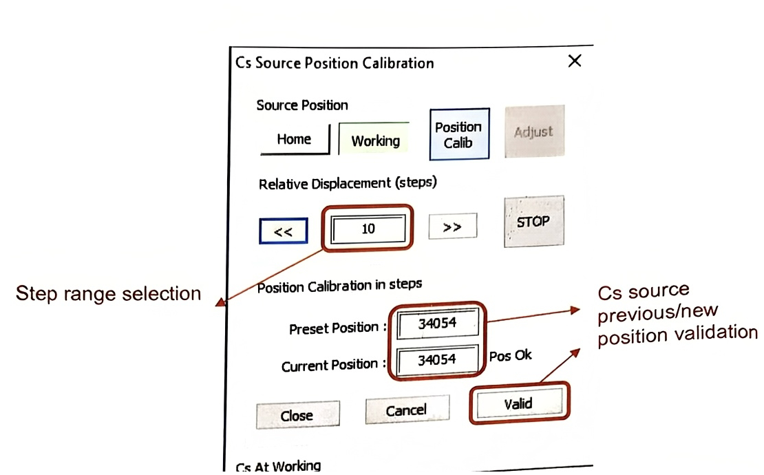
- Open ‘Cs Source Position Calibration’ panel from the Tuning menu:
Tuning → Setup → Cs Source Position Calibration like below.
-
Keeping Beam OFF, maximize the primary current by moving Cs position_ Relative Displacement (steps). Small step would be enough to start for example 10 steps to the left or right direction.
-
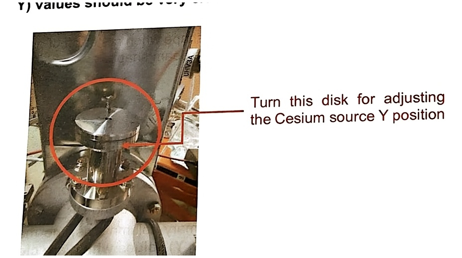
If X position is well turned at the maximum primary current, check Y position of Cs source. Refer to the picture below. Maximize the primary current by adjusting the height of Cs source manually.
-
If Cs source is well centered mechanically on the primary column axis, DP_3a (X, Y) values should be very close to zero.
STEP B: Alignment of the primary beam in D4 aperture
Section titled “STEP B: Alignment of the primary beam in D4 aperture”-
Turn ON the primary beam, center it in the FA plane using Beam pos (X, Y) deflectors. No problem to check this step with very small primary current as there is not yet L2 HV. Usually, the centering in D4 aperture is not different whatever L2 value is.
-
With Beam On, wobble L4. The beam should focus and defocus at the same place. If not, correct the alignment with D4 aperture positions (X, Y).
-
Re-center the beam on the secondary optical axis; at the center of the field aperture plane using Beam pos (X, Y).
-
Validate D4_750 μm (#1) position by clicking the [VAL] button on the ‘Mass & Apertures’ panel.
■ Note: The positioning for other D4 apertures will be covered in the following procedure STEP C.
STEP C: Alignment of the primary beam in Lens 2
Section titled “STEP C: Alignment of the primary beam in Lens 2”- Keep the beam focused in a small probe with L4, as set previously. With beam On, increase L2 slowly then wobble it. When wobble L2, the beam should focus and defocus at the same place. If not, use DP_3a (X, Y) to center it.
■ Note: It is probably necessary to adjust again the Cs source mechanical position X & Y if DP 3a values are very high. In this case, repeat STEP A described above. When the beam is well aligned in L2, we can see a halo image which is passing through the D4 aperture.
-
Set L2 value at your desired primary current and focus the beam on the sample surface with L4 lens.
-
Final adjustment to improve the beam shape using stigmators (Stig_45, Stig_90), quadrupole (D5-S1) and L4 focusing.
STEP D: Adjust/Validate the position of the D4 apertures
Section titled “STEP D: Adjust/Validate the position of the D4 apertures”- Until now, we have been working with D4=750 μ m (#1) while keeping D0=3000 μ m. To be able to change the primary current freely, all D4 aperture should be correctly aligned and be validated. Set D4=500 μ m (#2) while keeping D0=3000 μ m.
■ Note: It is recommended to write down the position (X, Y) of D4=750 μ m before change to another D4 aperture.
-
With Beam On, wobble L4. The beam should focus and defocus at the same place. If not, correct the alignment with D4 aperture positions (X, Y).
-
Re-center the beam on the secondary optical axis; at the center of the field aperture plane using Beam pos (X, Y).
-
Validate D4=500 μm (#2) position by clicking the [VAL] button on the ‘Mass & Apertures’ panel.
-
Change D4 aperture to the next one and repeat 2~4 for each D4 aperture.
■ Note: The X-position of D4 aperture is usually similar for all 6 apertures (< 1000 digits). Whereas the Y-position of D4 is different. Consecutive apertures have a difference about 1800 digits in y-axis.
- Set D4=750 μ m (#1) again after all validation.
STEP E: Centering/Validating the position of the D0 apertures
Section titled “STEP E: Centering/Validating the position of the D0 apertures”-
Until now, we have been working with D0=3000 μ m which means no aperture. To be able to change the primary current freely, all D0 aperture should be correctly aligned and be validated. Set D0=2000 μ m (#1) while keeping D4=750 μ m (#1) as set previously.
-
With Beam Off, adjust the position (X, Y) of D0 aperture to maximize the primary current.
-
Validate D0=750 μm (#2) position by clicking the [VAL] button on the ‘Mass & Apertures’ panel.
-
Change D0 aperture to the next one and repeat 2 & 3 for each aperture.
■ Note: The X-position of D0 aperture is usually similar for all 6 apertures (< 1000 digits). Whereas the Y-position of D0 is different. Consecutive apertures have a difference about 1800 digits in y-axis.
STEP F: Using the Wien filter
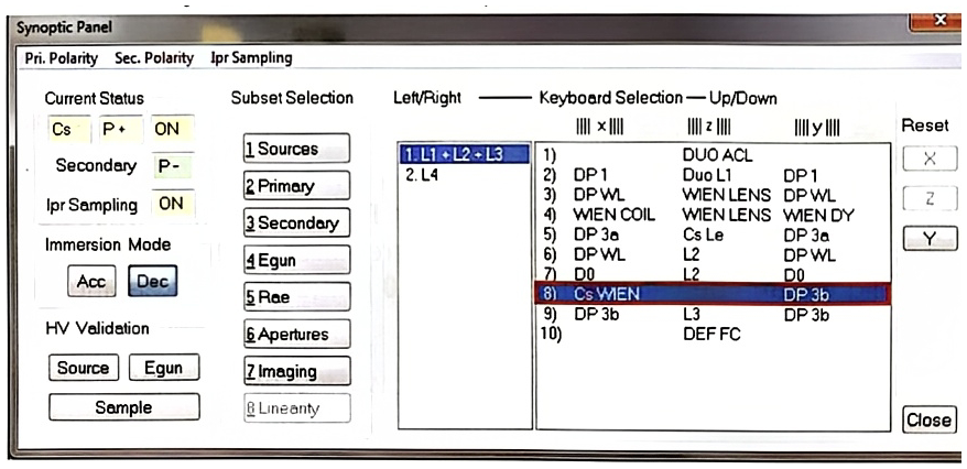
Section titled “STEP F: Using the Wien filter”- Open ‘Synoptic panel’ and select the corresponding menu as it is shown hereunder picture: 2. Primary → 1. L1+L2+L3 → 8) Cs WIEN, DP 3b
-
Set WIEN COIL = 2 Amp. When you increase the Wien coil value, the primary beam will move continuously along Y-axis.
-
In order to keep the beam inside of the FA plane, in other words; in order not to lose completely the beam on the MCP plate; use DP_3b (Y) deflector for bring it back to the center of the image gradually. The final value of DP_3b (Y) should be close to the typical value – 250 digits.
STEP G: Using L3 lens for higher primary current
Section titled “STEP G: Using L3 lens for higher primary current”-
Increase L3 HV slowly. As the L3 value increases, it is possible that the beam shape is deformed, and the beam position moves. The primary current also could be decreased.
-
Maximize the current using DP_3a (X, Y).
-
Repeat 1~2 until the desired current is reached.
■ Note: In general, the L3 HV is optimized about 30~40 % of source HV.
-
Bring the beam back to the center of the FA plane using Beam pos (X, Y).
-
Focus the beam as small as possible using L4 lens.
■ Note: No need to center the beam in D4 aperture while wobbling L4 mentioned in STEP A. As it is actually very difficult to align the primary optics with all four lenses (L1, L2, L3 and L4). Therefore, after L3 lens is applied, it is strongly recommended to keep all other parameters except L4 in order to focus the beam as small as possible.