8.1 Alignment procedure for Projection
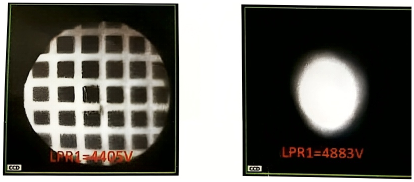
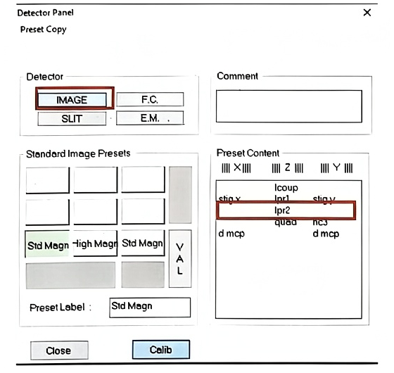
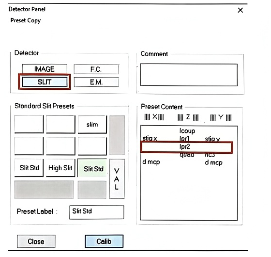
For a given magnification, the LPR2 value for both image mode and slit mode must be the same.
8.1.1 Instrument conditions
Section titled “8.1.1 Instrument conditions”Instrument condition: FA #1 (1800μm), CA #1 (400 μm), Max area (Transfer preset) 150 μm, Entrance Slit full open (400μm) and Exit Slit full open (1200 μm).
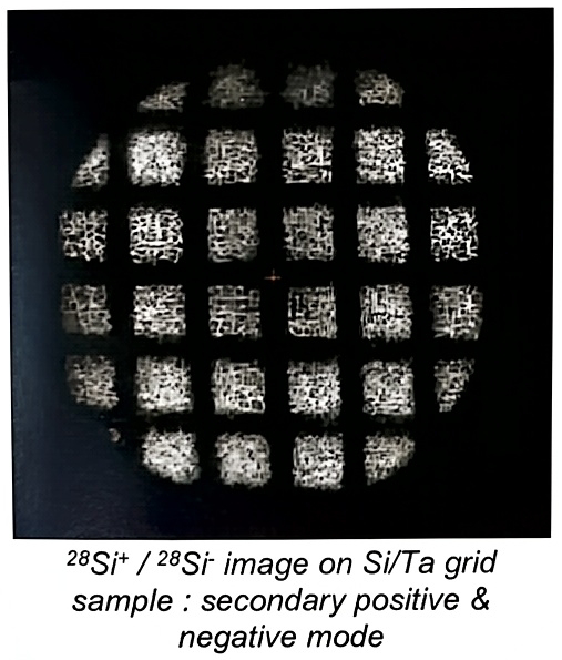
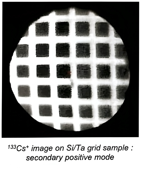
It is previously needed to prepare a clear grid image on Image mode as it is shown below.
8.1.2 Alignment procedure
Section titled “8.1.2 Alignment procedure”Setting DPRY
-
Open the MCP Image calibration box while keeping grid image on Image mode.
-
Increase LPR1 to have slit mode, if the beam is not wobbling at the same position between Image and Slit mode, recenter it using Mass field for horizontal centring and DPRY for vertical centring.
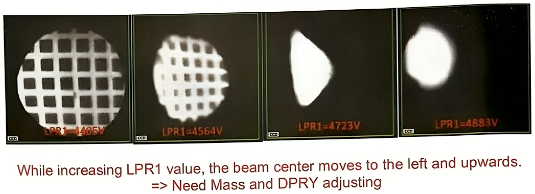
- Note that the previous procedure 2) can be simply performed by alternating both Image preset & Slit preset. Refer to the images below when DPRY is not correctly set.
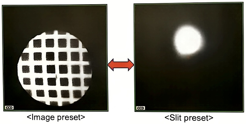
- After adjusting the Mass for horizontal centring and DPRY for vertical centring, both shapes should be set at the same position.