8.4 Alignment procedure for Energy Slit and Detectors
8.4.1 Energy Slit width and centering
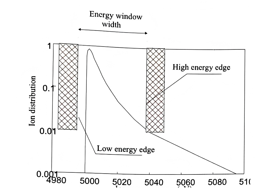
Section titled “8.4.1 Energy Slit width and centering”The Energy Slit device consists of two bars driven independently along the X axis. The Energy window width W is defined by the distance between both inner bar edges. Both moving bars are controlled though bound up parameters: Position and width. When the Energy Slit is varied, both bar position are moved simultaneously of the same step while when the Energy Slit width W is varied, only the Energy Slit bar corresponding to the high energy bar (outer bar) is moved. The Energy Slit preset contains both the Energy Slit position and width.
The Energy Slit is normally used for limiting the ion high energy, as it is shown in the sketch below.
Setting Energy Slit X using Scan All tool
Section titled “Setting Energy Slit X using Scan All tool”-
Select a species with a narrow energy distribution width ( ²⁸Si⁺/⁻ for secondary positive & negative mode, ¹³³Cs⁺ for MCs ⁺ mode).
-
Select a detection mode (EM or FC) depends on the signal level.
-
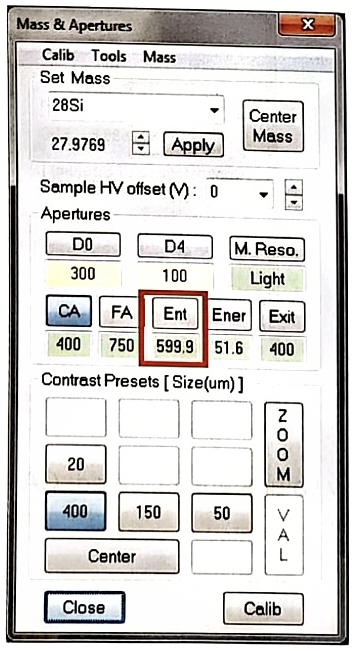
Click the Energy Slit preset from ‘Mass & Apertures’ panel.
-
Select a desired preset of Energy Slit width (ex: 50eV).
-
Open Scan All software from IMS ‘Board’ menu.
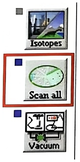
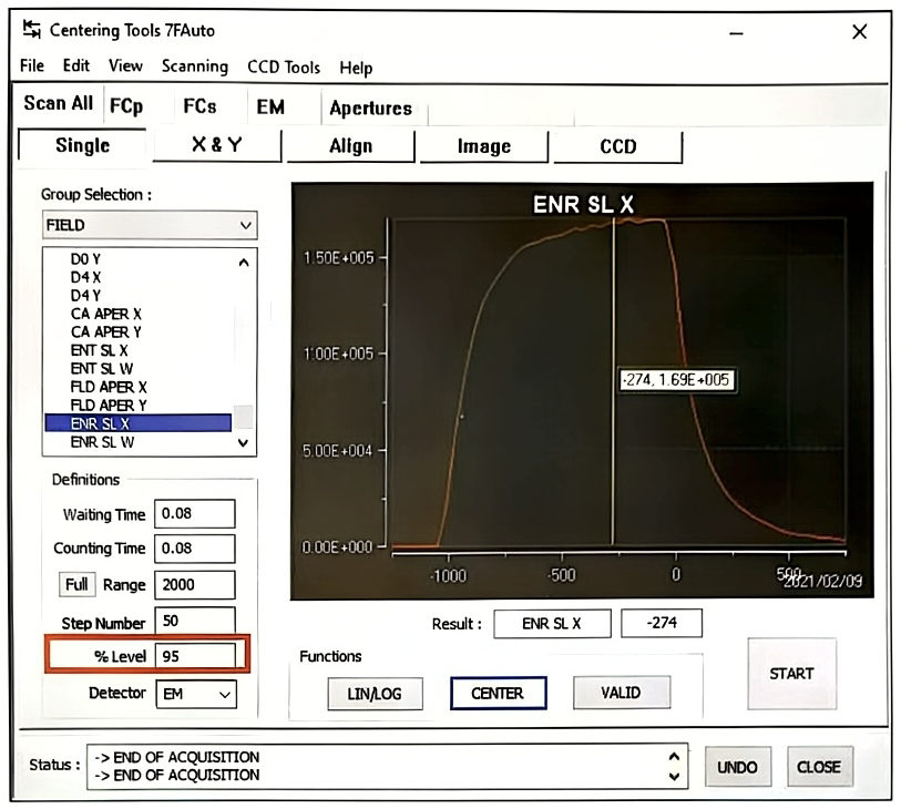
- Select Scan All menu/Single/ENR SL X like below.
-
‘Scan range’ must be adjusted depends on the given conditions. It is good to start and finish with zero signal, it means that left side and right side of the scan shape as shown in the figure above. This is typical shape of Energy slit X scan which is not symmetric.
-
Detector can be selected between EM and FC depends on the signal level.
-
Note that % Level must be set to 95% for Energy Slit scan in order to find both a good center and a gap voltage at the same time.
-
Click ‘Start’ button then Scan All performs a scan. You can stop it whenever during the scan. We recommend you stop after 1 or 2 scan sequences.
-
Click ‘Center’ then, the yellow cursor will be automatically placed at the peak width at 95% height of maximum signal. Then click ‘Valid’ button.
-
Return to the ‘ENR’ preset from ‘Mass & Apertures’ panel. Validate the working preset of Energy Slit Width (ex: 50 eV). Note that the ‘Valid’ from Scan All does not save preset itself. Therefore, the validation must be done manually.
-
If needed, this procedure must be done for each different Energy Slit Width (ex: 75 eV, 25 eV etc).
Note: For the detail information about the utilization of Scan All software, refer to the IMS 7f-Auto Software users guide-Scan All.doc.
8.4.2 Centering of EXIT ESA and Detectors
Section titled “8.4.2 Centering of EXIT ESA and Detectors”Now, the well-aligned secondary signals are just before reaching the detector. At this last point, it would be a pity to lose the signal because the entrances of the detectors are not well centered. This step can be done with Scan All tool again.
Setting EXIT ESA using Scan All tool
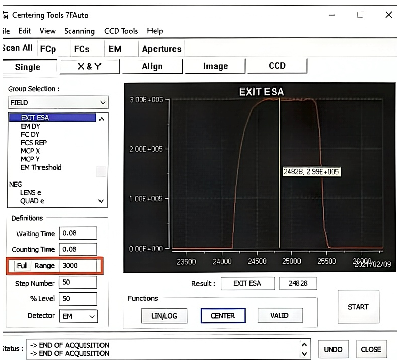
Section titled “Setting EXIT ESA using Scan All tool”- Select Scan All menu/Single/EXIT ESA like below.
-
‘Scan range’ must be adjusted depends on the given conditions. It is good to start and finish with zero signal, it means that left side and right side of the scan shape as shown in the figure above.
-
Detector can be selected between EM and FC depends on the signal level because EXIT ESA value is the same for both EM and FC detectors.
-
Note that % Level is typically set to 50% for EXIT ESA in order to find the centering at FWHM (Full Width at Half Maximum) position because the scan shape is symmetric.
-
Click ‘Start’ button then Scan All performs a scan. You can stop it whenever during the scan. We recommend you stop after 1 or 2 scan sequences.
-
Click ‘Center’ then, the yellow cursor will be automatically placed at the center of 50% height of maximum signal. Then click ‘Valid’ button. This ‘Valid’ order will automatically validate EM/FC detector preset.
Setting EM-DY using Scan All tool
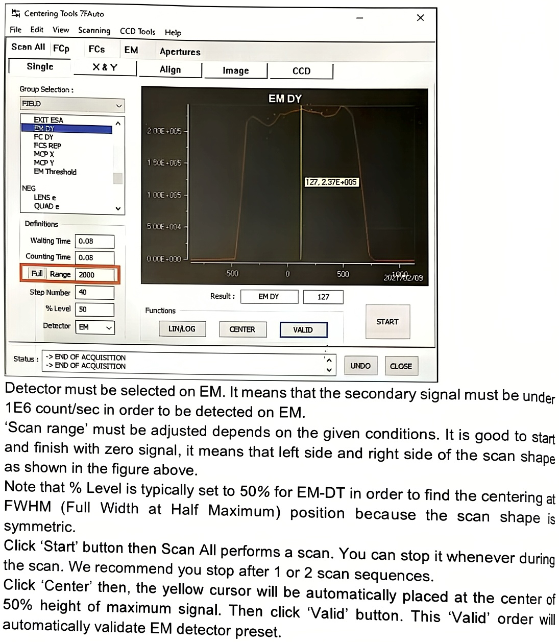
Section titled “Setting EM-DY using Scan All tool”- Select Scan All menu/Single/EM DY like below.
-
Detector must be selected on EM. It means that the secondary signal must be under 1E6 count/sec in order to be detected on EM.
-
‘Scan range’ must be adjusted depends on the given conditions. It is good to start and finish with zero signal, it means that left side and right side of the scan shape as shown in the figure above.
-
Note that % Level is typically set to 50% for EM-DY in order to find the centering at FWHM (Full Width at Half Maximum) position because the scan shape is symmetric.
-
Click ‘Start’ button then Scan All performs a scan. You can stop it whenever during the scan. We recommend you stop after 1 or 2 scan sequences.
-
Click ‘Center’ then, the yellow cursor will be automatically placed at the center of 50% height of maximum signal. Then click ‘Valid’ button. This ‘Valid’ order will automatically validate EM detector preset.
Setting FC-DY using Scan All tool
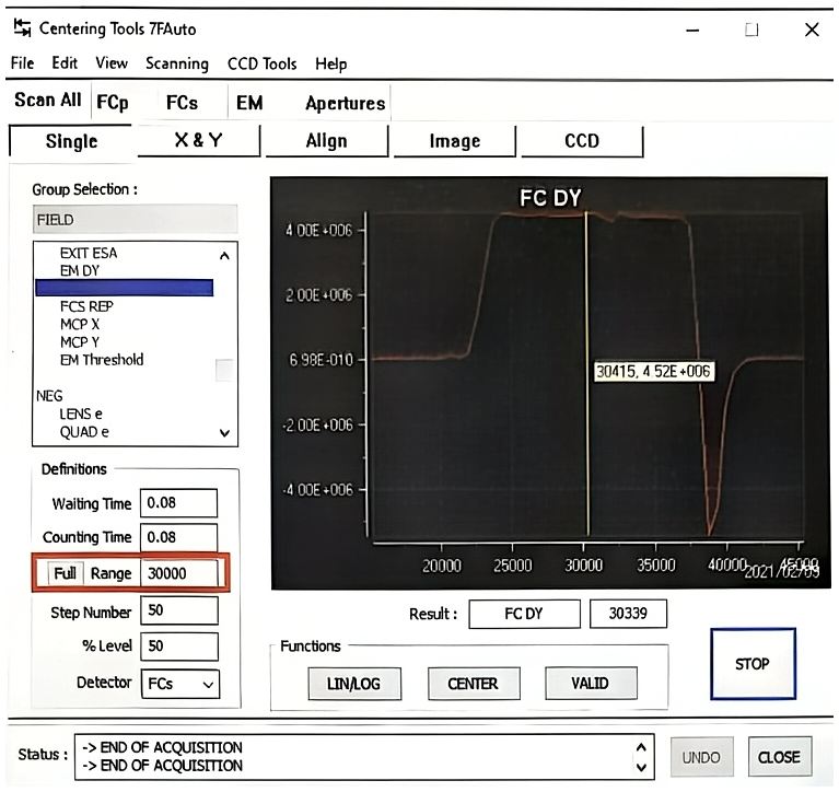
Section titled “Setting FC-DY using Scan All tool”- Select Scan All menu/Single/FC DY like below.
-
Detector must be selected on FC. It means that the secondary signal must be over 1E6 count/sec in order to be detected on FC.
-
‘Scan range’ must be adjusted depends on the given conditions. It is good to start and finish with zero signal, it means that left side and right side of the scan shape as shown in the figure above.
-
Note that % Level is typically set to 50% for FC-DY in order to find the centering at FWHM (Full Width at Half Maximum) position because the scan shape is symmetric.
-
Click ‘Start’ button then Scan All performs a scan. You can stop it whenever during the scan. We recommend you stop after 1 or 2 scan sequences.
-
Click ‘Center’ then, the yellow cursor will be automatically placed at the center of 50% height of maximum signal. Then click ‘Valid’ button. This ‘Valid’ order will automatically validate FC detector preset.